State estimation · 2023
Rover Sensor Fusion & Localization
A custom Raspberry Pi/Navio2 sensor stack and 16-state Unscented Kalman Filter for mobile-rover odometry.
01
Overview
This project combined the complete embedded sensing chain: construction of the rover test hardware, direct acquisition and calibration of its navigation sensors, ROS integration, and implementation of an Unscented Kalman Filter for localization. Two suspended rover platforms were used so the estimator depended on general rigid-body kinematics rather than a vehicle-specific wheel or suspension model.
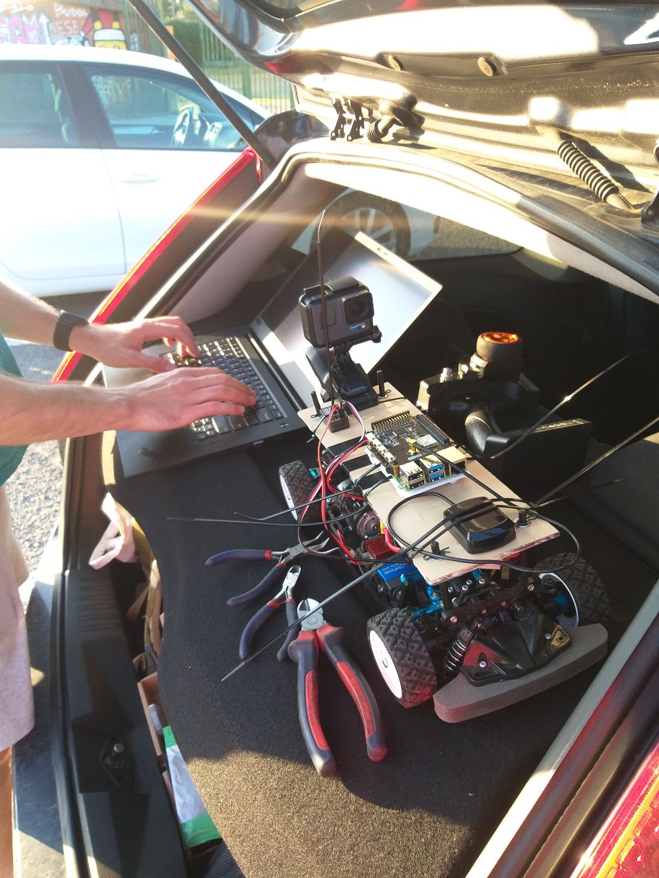
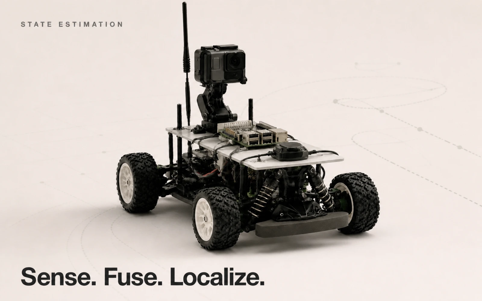
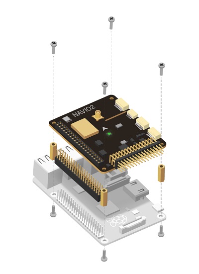
The mobile platform was built around a four-wheel RC chassis with independent suspension and an added two-level test deck. A Raspberry Pi 4 provided the Linux/ROS computer, while a Navio2 expansion board supplied the MPU9250 accelerometer, gyroscope, and magnetometer together with GNSS and barometric sensing. The open deck kept the boards, power distribution, external antennas, wiring, and camera accessible during field debugging and made it possible to move the same navigation stack between rover chassis.
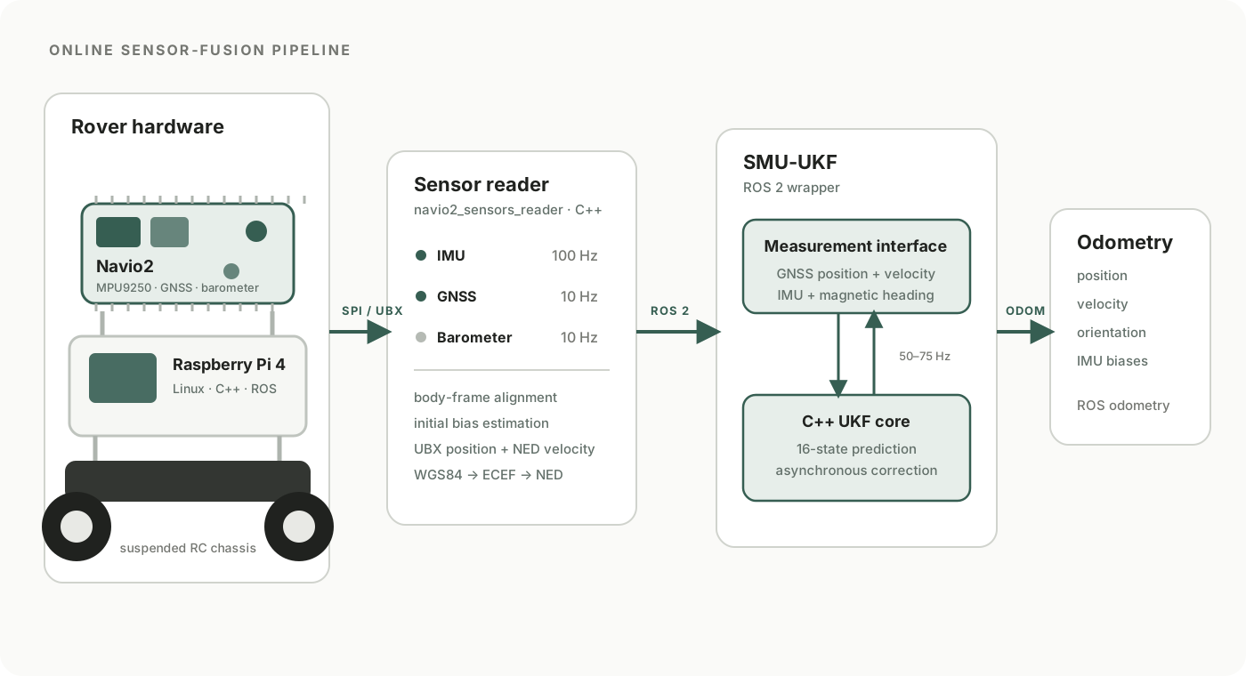
Instead of using ArduPilot and MAVLink—which limited IMU delivery to roughly 40 Hz in this setup—I developed a custom C++ navio2_sensors_reader package. It acquired raw inertial data directly over SPI at 100 Hz, aligned each sensor with the selected body coordinate frame, and published the results through ROS. I also extended the low-level u-blox interface to request GNSS velocity in the NED frame through UBX-NAV-VELNED. Latitude, longitude, and altitude were converted from WGS84 through ECEF into a local North-East-Down frame whose origin was established by the first valid GNSS fix.
The 16-state SMU-UKF estimated three-dimensional position and velocity, quaternion orientation, accelerometer bias, and gyroscope bias. Accelerometer and gyroscope measurements propagated the state; GNSS position and velocity corrected inertial drift, while magnetometer data and the WMM2020 magnetic declination model supplied a geographic heading correction. Initial accelerometer and gyroscope offsets were measured online while the stationary rover collected a configurable sample window. A separate hard-iron calibration, implemented and cross-checked in C++ and MATLAB, corrected the magnetometer.
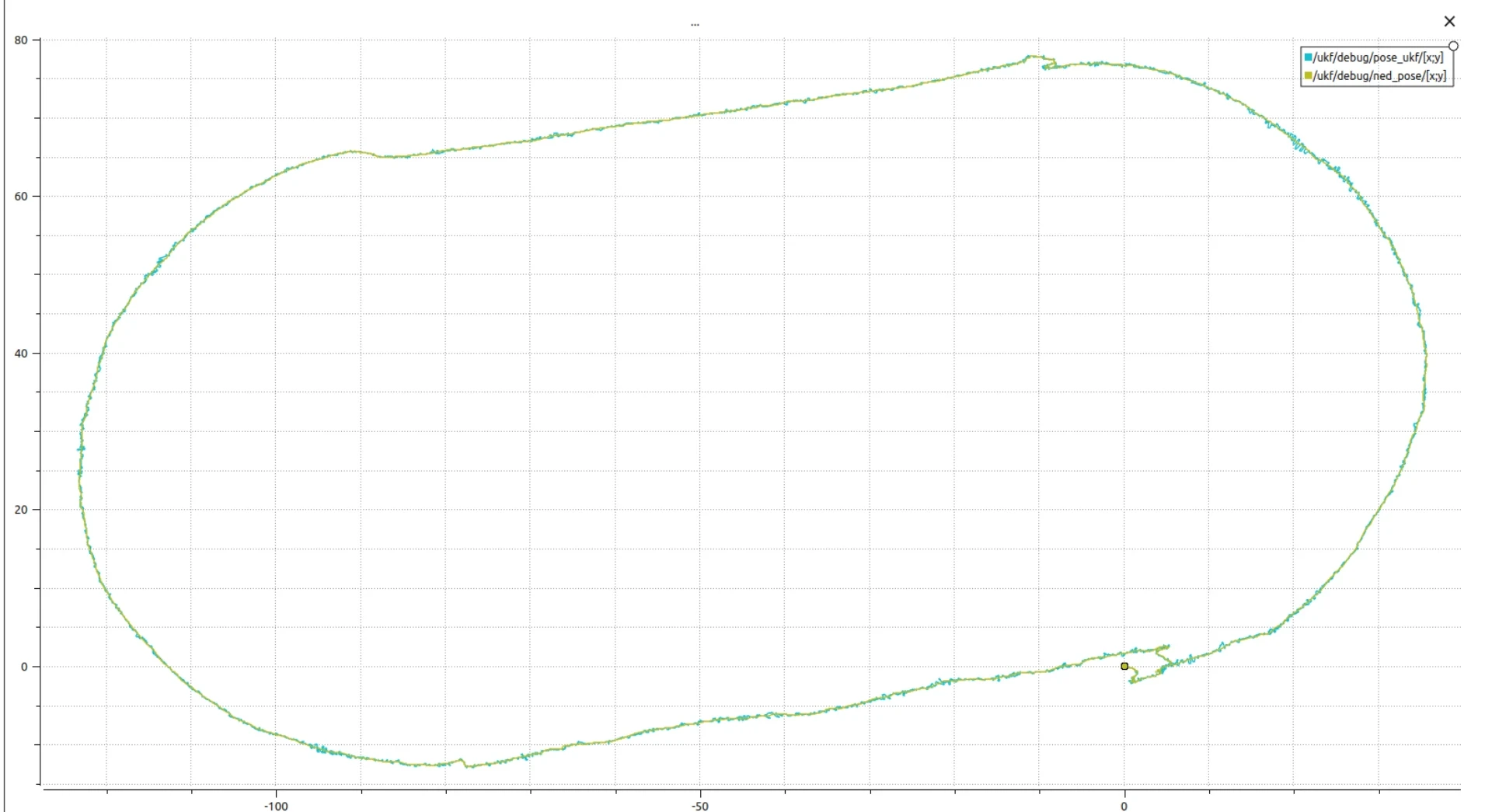
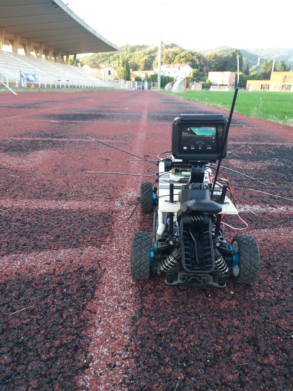
The software supported both real-time operation and faster-than-real-time replay from ROS bags. Testing progressed from stationary boards and short parking-lot paths to repeatable oval and circular trajectories on an athletics track. At the final revision, the filter ran at 75 Hz compared with the GNSS receiver’s 10 Hz updates and handled simulated GNSS interruptions lasting a few seconds. Its estimates were comparable to GNSS rather than consistently better: vertical motion, attitude, and inertial-bias convergence remained the main limitations. Those results identified the next steps clearly—fusing barometric altitude, improving magnetic filtering, and adding roll and pitch measurements to the correction vector.
02
My contribution
- Built and instrumented suspended RC-rover test platforms around a Raspberry Pi 4, Navio2 board, external navigation hardware, and an accessible two-level electronics deck.
- Developed the C++ navio2_sensors_reader ROS package for direct SPI acquisition of accelerometer, gyroscope, and magnetometer data at 100 Hz.
- Extended the low-level GNSS interface to read UBX position and NAV-VELNED velocity messages, then implemented WGS84-to-ECEF-to-NED conversion around the first valid fix.
- Implemented a 16-state Unscented Kalman Filter for position, velocity, quaternion orientation, accelerometer bias, and gyroscope bias.
- Calibrated the inertial and magnetic sensors and validated the estimator online and through recorded ROS bags on oval and circular rover trajectories.
03
System architecture
A Raspberry Pi 4 and Navio2 board formed the rover’s embedded navigation computer. The custom C++ sensor reader bypassed the slower ArduPilot/MAVLink path, published raw sensor data through ROS, and fed a 16-state UKF that estimated position, velocity, orientation, and inertial-sensor biases.
04
Technical details
Rover hardware
The Raspberry Pi/Navio2 stack was mounted above a four-wheel suspended RC chassis, with an open test deck for antenna placement, power, cabling, debugging, and synchronized camera recording.
Direct sensor access
Reading the MPU9250 through a custom SPI interface raised IMU acquisition from the 40 Hz MAVLink path to 100 Hz and gave full control over axes, frames, and timestamps.
Navigation filter
Inertial data drove the prediction step; GNSS position and velocity plus magnetometer-derived heading corrected drift. The barometer was published but not fused in the evaluated filter.
Calibration and validation
Stationary averaging estimated initial IMU offsets, hard-iron calibration corrected the magnetometer, and online plus rosbag tests supported covariance tuning and fault investigation.
05
Technologies
06
Media